Compact Size
Robust construction and several ring-gears engagement make the considerably lighter and more compact ROLADRIVE reducer. The brainchild compact motor downsize 50%-60% than conventional reducers.
High Efficiency
External and internal ring gears are around able units contact by rolling when engage. It reduces sliding friction loss when engage and obtains especially high efficiency. 90% efficiency ratio is obtained in single reduction while 80% in double reduction.
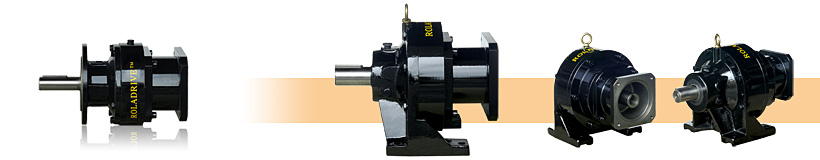
Vertical & Horizontal motor type one stage reducer
|
Vertical & Horizontal double shaft type two stage reducer